


From Workbench to Enclosure: What Changes Monochrome Display Readability?
On the workbench, the numbers are easy to read. Inside the finished equipment, they become faint when the operator stands to one side. Under another light source, the protective window reflects more of the room than the screen.
The module has not necessarily failed. Its installed viewing conditions have changed.
Monochrome display readability is a property of the complete viewing arrangement, not just the bare LCD. The module, enclosure, illumination, screen content, and user's position all contribute to the result. For an OEM design review, the useful question is therefore not simply “Does the display look clear?” It is “Can the intended user read the required information under the conditions in which the equipment will operate?”
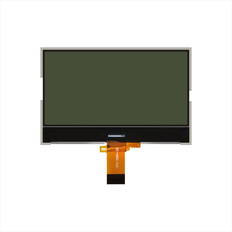
The Workbench Is Only One Viewing Condition
Bench testing often places the observer close to the screen, at a comfortable angle, under convenient room lighting. The module may be outside its enclosure, with no protective window or surrounding bezel.
The final product can change every part of that arrangement. A wall-mounted controller may be above the user's eye level. A handheld instrument may be tilted during use. A recessed panel may cast a shadow, while a window introduces reflections that were absent during development.
A clear bench image establishes that the chosen setup can produce a readable result. It does not establish that the installed assembly meets the application's viewing requirements.
Define the Reading Task Before Comparing Samples
Identify what the user must recognize: a large operating value, a short status message, a small unit symbol, or a dense menu. These tasks do not place the same demands on the screen layout.
- Who reads the display, and from which standing, seated, or handheld position?
- What is the expected reading distance and range of movement?
- Which values, symbols, or messages are essential to the task?
- Under which lighting conditions must the information remain readable?
- Does the user need to identify information at a glance, or inspect a menu at close range?
These answers turn an informal opinion about appearance into a testable design brief.
Viewing Direction Belongs in the Mechanical Drawing
Many monochrome LCD specifications identify a preferred viewing direction using clock positions, such as 6:00 or 12:00. This describes an orientation associated with the panel's viewing characteristics; it is not a claim that the screen can be seen only from one point.
Interpret Clock Positions from the Defined Front View
In the conventional front-view description, a 6:00 direction is toward the bottom of the display, while 12:00 is toward the top. Check the manufacturer's drawing and optical information before applying that description to the equipment.
Do not infer the preferred viewing direction from connector location. Also distinguish the direction of best contrast from the full range over which the application finds the display acceptable.
Panel Tilt Changes the User's Relationship to the LCD
A module mounted vertically and the same module mounted on an angled control panel present different viewing geometry. Equipment height and user position can move the normal operating view away from the favorable direction.
Review the actual installation in a mock-up or prototype. Mark the display orientation and representative user positions so that the same geometry can be reproduced during later tests.
If a design relies on rotating the module, check both the optical orientation and the firmware's ability to present the required content. Rotating an image in software does not change the LCD's physical viewing characteristics.
Consider Where the Useful Light Comes From
Reflective, transmissive, and transflective describe how an LCD uses light. They are useful starting points for a test plan, but they do not replace an evaluation of the selected module.
| Optical arrangement | Basic light path | Design-review question |
|---|---|---|
| Reflective | Uses incident light reflected back through the display. | Does sufficient useful light reach the installed display at the intended viewing position? |
| Transmissive | Uses illumination transmitted from a backlight. | Does the backlit image remain readable against the ambient light and surface reflections? |
| Transflective | Combines reflective and transmissive light paths. | How does the actual assembly perform in both bright ambient light and backlit low-light operation? |
Do Not Treat “Transflective” as an Outdoor Approval
A transflective arrangement can use ambient light as well as backlighting, but the label alone does not establish acceptable performance in every outdoor position.
The installed window, reflections, incident-light direction, viewing position, and screen content still matter. If direct-sunlight use is part of the product requirement, include that condition in the evaluation rather than relying on the optical label.
Increasing Backlight Output Is Not Always the Right Change
More illumination may help under some conditions, but it does not remove a reflection from a cover window or correct an unfavorable viewing direction. It can also affect the power and thermal requirements of the assembly.
Compare approved backlight settings while holding the other test conditions constant. Keep backlight brightness separate from LCD contrast or drive adjustments; they are not interchangeable controls.
For terminology, the article on LCD luminance and measurement units provides background. Brightness values alone, however, do not describe the user's complete reading experience.
The Enclosure Becomes Part of the Optical System
A protective window serves a mechanical purpose, but it also changes the path of light between the observer and the LCD. Evaluate the specified production material, tint, finish, and geometry rather than assuming any transparent sample is representative.
Compare the Bare Module with the Installed Assembly
Use the same display content, observer position, and lighting for both conditions. A controlled comparison helps identify what the installation adds to the problem.
| Comparison | Observation to record | Design item to review |
|---|---|---|
| Bare module versus module behind the window | Change in visibility, apparent contrast, reflections, or image quality | Window material, tint, finish, angle, and separation from the LCD |
| Open mock-up versus finished bezel | Shadows, clipping, or restricted off-axis visibility | Opening size, recess depth, and bezel geometry |
| One light position versus another | Reflections crossing important information | Installation orientation and reflected-light path |
| Clean reference window versus expected use condition | Effects of representative surface marks or contamination | Surface treatment, cleaning instructions, and maintenance expectations |
Look for Reflections from the User's Position
A window may look clear when inspected from above but reflect an overhead luminaire directly toward a seated operator. Observe the assembly from the intended eye positions.
If a reflection obscures a critical value, record the light-source position and window angle. Changing the LCD module before reviewing that geometry may leave the same problem in place.
Check the Opening, Not Just the Screen Size
A deep recess or narrow bezel opening can restrict off-axis viewing or shade part of the display. Confirm that the required content remains visible throughout the intended viewing range.
Use the finished mechanical arrangement for approval. A prototype with a wider opening or shallower recess may give an overly favorable result.
Test the Interface People Will Actually Read
A large demonstration number is useful during development, but it may conceal weaknesses in the production interface. The smallest unit symbol, longest menu label, or most crowded status screen may be the more demanding test.
Use Representative Fonts and Symbols
Display the actual character sizes, stroke patterns, decimal points, units, and icons intended for release. Include combinations that could be confused at the required distance.
For graphic modules, pixel resolution does not by itself establish legibility. The way those pixels are used remains a design decision. For character modules, confirm that the available character shapes and layout suit the task.
Include Critical Messages and Dense Screens
Review routine screens as well as important status or fault messages. An interface that is readable during normal operation should not be assumed to handle every message equally well.
Where the equipment has safety-related information, use the applicable system-level design and validation process. A general readability check is not a substitute for that assessment.
Build a Readability Test Matrix That Can Be Repeated
The purpose of a matrix is to make comparisons fair and preserve the conditions behind each result. It does not need to test every possible combination, but it should cover the intended use and the conditions most likely to expose a problem.
| Test field | What to document |
|---|---|
| Assembly | Module part number, orientation, enclosure revision, window material, and bezel configuration |
| Viewing position | Reading distance, horizontal and vertical position, and panel tilt |
| Lighting | Source type, direction, relevant intensity measurements where available, and test location |
| Display operation | Backlight setting, approved contrast setting, screen content, and relevant operating conditions |
| Task | The exact value, symbol, or message the observer must identify |
| Result | Reading outcome, errors or difficulty, measured data where applicable, and photographs |
Separate User Reading Checks from Instrument Measurements
An instrument can quantify a defined optical property under a specified geometry. A reading task assesses whether the intended information can be recognized under the test conditions. These provide related but different evidence.
Use an agreed measurement method where numerical optical limits are required. Do not invent one universal luminance, contrast, or distance threshold for all monochrome display applications.
Use Photographs as Records, Not as the Only Verdict
Camera exposure, focus, processing, and viewpoint can change how readable a screen appears. A photograph that looks clear is not proof that the installed screen passes the intended task.
For before-and-after records, keep the camera arrangement and settings consistent where practical, and retain the observations or measurements that support the decision.
Decide Which Part of the Design Needs to Change
Consider a hypothetical controller that passes a front-facing bench check but becomes difficult to read inside a tilted panel. The initial response might be to request a brighter backlight.
A more informative comparison holds the display settings constant and evaluates the assembly with and without its window, then from the intended operating position. If the main change follows a reflected light source or an unfavorable view, the solution may involve enclosure geometry or module orientation rather than additional illumination.
This is an illustrative design situation, not a RONDELI customer case or a claim about a particular product.
Define the user's reading task and installed position
↓
Reproduce the relevant lighting and assembly conditions
↓
Separate viewing-direction, window, illumination, and UI effects
↓
Make a documented design change
↓
Repeat the affected tests and confirm the complete assembly
When the evidence points to module configuration, the monochrome display options for embedded equipment provide a starting point for reviewing alternatives. Supply the viewing geometry, enclosure information, and test findings so that the requirement is more specific than “a clearer screen.”
If there is no valid image even under a known suitable bench condition, use the monochrome LCD blank-screen troubleshooting guide before treating the issue as an installed-readability problem.
Frequently Asked Questions
Why Is a Monochrome Display Clear from One Direction but Not Another?
The panel's optical characteristics can produce different contrast at different viewing positions. Check the specified viewing direction, the module orientation, and the actual user position rather than judging the display only from directly in front.
Does a Brighter Backlight Always Improve Readability?
No. It may help under some conditions, but it does not remove window reflections, change the panel's viewing direction, or enlarge a small symbol. Identify the limiting factor before changing illumination.
Is Every Transflective LCD Readable in Direct Sunlight?
The optical arrangement can use ambient light, but acceptable performance still depends on the specific module and installation. Evaluate the intended sunlight condition, viewing position, window, and content before approving the assembly.
Can a Cover Window Make an Otherwise Clear LCD Difficult to Read?
Yes. Reflections, tint, surface condition, and installation geometry can affect the view. Compare the same module with and without the specified window under otherwise unchanged conditions.
Should Readability Be Approved Before the Enclosure Is Finished?
Early checks are valuable, but final approval should represent the production assembly. Changes to the window, bezel, recess, or mounting angle may alter the result and require relevant tests to be repeated.
What Should a Monochrome LCD Readability Report Include?
Record the module and assembly revisions, viewing positions, lighting conditions, display settings, representative screens, acceptance criteria, and results. Include photographs as supporting records and identify any conditions not covered by the evaluation.