


TFT LCD Module Integration: From Sample Evaluation to Mass Production
Selecting a display is only the beginning of a successful product. Turning a TFT LCD module into a fully integrated, reliable component inside your device requires a structured process — from defining requirements and evaluating samples, through mechanical and touch integration, to reliability validation and mass production planning.
Many display-related project delays and costly redesigns happen not because the wrong display was chosen, but because integration issues were discovered too late: an FPC that collides with the enclosure, a touch controller that conflicts with the mainboard, or a reliability test that fails just before launch. This guide walks through the complete TFT LCD module integration process in six phases, with practical checklists and a real-world case study to help you avoid those pitfalls.
For a broader overview of display selection criteria — size, resolution, brightness and application matching — see our TFT LCD Module landing page. This article focuses specifically on what happens after you have a shortlist: how to take a module from sample to mass production.
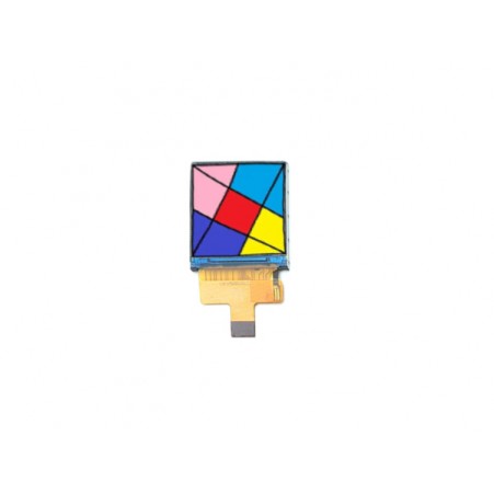
Why integration planning matters more than display specs alone
A display module does not exist in isolation. It interacts with your mainboard, enclosure, power system, firmware and assembly process. A module that looks perfect on a datasheet can still fail in the field if integration details were not planned early.
Common late-stage integration failures
- FPC direction or connector position conflicts with the enclosure, forcing a mechanical redesign.
- Touch controller IIC address conflicts with another peripheral on the same bus.
- Cover lens thickness or air gap causes optical issues (moiré, reduced brightness, parallax).
- Reliability testing reveals failures only after tooling is committed.
- Supply chain gaps appear when the chosen module reaches end-of-life mid-production.
The cost of late discovery
Fixing an integration issue at the sample stage might cost a week and a revised FPC. Discovering the same issue after tooling or during mass production can cost months and significant rework. Early, structured integration planning is the cheapest insurance you can buy.
Phase 1: Define display requirements before requesting samples
The quality of your sample evaluation depends entirely on how well you define requirements upfront. A vague request leads to a vague sample, which leads to a vague evaluation.
Build a requirement checklist
Before contacting a supplier, fill out a simple requirement sheet covering these categories:
| Category | Must-have items | Nice-to-have items |
| Display | Size, resolution, interface, brightness | IPS, viewing angle, color gamut |
| Touch | Capacitive/resistive, multi-point, IIC/USB | Gesture support, glove/wet hand |
| Mechanical | Outline, active area, FPC direction | Cover lens, logo printing |
| Environment | Operating temp, storage temp | Vibration, ESD, humidity |
| Supply | MOQ, lead time, lifecycle | Custom packaging, documentation |
Separate must-have from nice-to-have
Not every requirement carries the same weight. Distinguishing "must-have" from "nice-to-have" helps your supplier propose the right module faster and gives you room to trade off when a perfect match does not exist. For example, if 500 nits is a must-have but IPS is nice-to-have, a TN panel with 500 nits may be a better fit than holding out for an IPS version that stretches your budget or timeline.
What to prepare before requesting a sample
- Your mainboard or SoC model and its native display interface.
- Target display size, resolution and brightness requirement.
- Mechanical constraints: available outline, FPC exit direction, connector position.
- Touch requirements: technology, multi-point, controller preference.
- Environmental requirements: temperature range, vibration, ESD exposure.
- Estimated annual quantity and target launch date.
Providing this information upfront allows a supplier to recommend a matching module or propose a custom configuration, rather than sending a generic sample that may not fit. Our TFT LCD Module landing page includes a detailed inquiry checklist you can use as a template.
Phase 2: Sample evaluation and bring-up testing
Once you receive a sample, the goal is to answer one question: does this module work in my system as intended? A structured bring-up test catches issues while they are still cheap to fix.
Bring-up test checklist
- Display: Confirm the image appears correctly — resolution, color order, orientation, brightness levels.
- Touch: Test single-touch, multi-touch, edge response and (if relevant) glove or wet-hand operation.
- Backlight: Verify PWM dimming works smoothly across the full range.
- Interface: Confirm stable communication at the target resolution and refresh rate, with no flickering or artifacts.
- Power: Measure actual power consumption at typical and maximum brightness; compare against your power budget.
Common sample-stage issues and how to document them
- Image shifted or wrong colors: Usually a timing or pixel-format mismatch — document the exact symptom and your mainboard configuration.
- Touch not responding: Check IIC address, interrupt pin and driver firmware — document the touch IC and host controller details.
- FPC does not fit: Note the exact interference point and share a photo or CAD file with your supplier.
- Brightness lower than expected: Measure with a lux meter at a defined distance and compare against the spec sheet.
Document every issue with photos, measurements and your test setup. This makes the feedback loop with your supplier much faster and more precise.
For a typical RGB-interface module used in POS and industrial applications, see our 7.0 inch RGB TFT LCD module.
Phase 3: Mechanical and optical integration
Once the module works electrically, the next challenge is making it fit — physically and optically — inside your product.
FPC direction, connector placement and cable routing
- Confirm the FPC exit direction (top, bottom, left, right) matches your enclosure's internal layout.
- Check connector placement does not interfere with other components or assembly steps.
- Plan cable routing to avoid sharp bends, pinching or interference with antennas.
- If the standard FPC direction does not fit, request a custom FPC with a different exit direction or length.
Cover lens, air gap and optical bonding
- Confirm cover lens thickness and material (PMMA vs glass) match your durability and optical requirements.
- Check air gap between the LCD and cover lens — too large causes parallax and reduced clarity; too small risks interference.
- For premium products, consider optical bonding (OCA or OCR) to eliminate the air gap, improving contrast and reducing reflections.
- Confirm surface treatment (anti-glare, anti-fingerprint) matches your usage environment.
Enclosure fit and assembly tolerance
- Verify the module outline fits your enclosure cut-out with proper tolerance (typically ±0.1-0.2mm).
- Plan mounting method: adhesive, screws, clips or a combination.
- Consider thermal expansion and contraction across your operating temperature range.
- Plan for assembly access — can the module be installed and removed without disassembling the whole device?
For a deeper understanding of how LCD modules are constructed — which helps explain why air gap and bonding matter — see our article on LCD TFT display structure.
Phase 4: Touch panel integration
Touch is often treated as an afterthought, but it has its own integration challenges that deserve dedicated attention.
Capacitive vs resistive touch: when to choose which
- Capacitive: Best for multi-touch, gesture support, high clarity and modern user expectations. Standard for POS, tablets, smart home and automotive.
- Resistive: Best for glove operation, wet environments, stylus input and cost-sensitive designs. Still common in industrial and medical equipment.
Touch controller, IIC address and firmware driver
- Confirm the touch controller (e.g., GT911, GT9271, FT5x06) IIC address does not conflict with other devices on the same bus.
- Verify the interrupt (IRQ) pin is connected and configured in your firmware.
- Check that a driver exists for your OS (Android, Linux, RTOS) or that you need to write one.
- Confirm touch coordinate mapping matches your display orientation and resolution.
Touch performance validation
- Test touch accuracy across the full active area, especially edges and corners.
- Test multi-touch gestures (pinch, swipe, rotate) if your application needs them.
- Test with gloves, wet fingers or stylus if relevant to your use case.
- Test after cover lens bonding — bonding can sometimes affect touch sensitivity.
For an example of a standalone capacitive touch panel that can be paired with an LCD module, see our 12.3 inch capacitive touch screen.
Phase 5: Reliability and validation testing
A display that works on the bench may still fail in the field. Reliability testing bridges that gap.
Temperature cycling, vibration, ESD and aging tests
- Temperature cycling: Verify the module survives repeated transitions between your operating temperature extremes (e.g., -20°C to +70°C).
- Vibration: Especially critical for automotive, portable and industrial applications — test per your target standard (e.g., IEC 60068).
- ESD: Test contact and air discharge per IEC 61000-4-2 to ensure the module survives real-world electrostatic events.
- Aging: Run extended operation tests to check for backlight degradation, image retention or contrast drift over time.
What test reports to request from your supplier
- Temperature cycling test report with pass/fail criteria.
- Vibration test report per your target standard.
- ESD test report with discharge levels and results.
- Aging/lifetime test data for the backlight and overall module.
- RoHS, REACH and other compliance documentation as needed.
Pass/fail criteria alignment with your end product
Align test criteria with your end product's real-world usage, not just generic industry standards. A display for a stationary industrial panel and one for a handheld device used outdoors face very different stresses. Discuss your specific use case with your supplier to define appropriate test levels.
For a detailed look at ESD testing specifically, see our guide on LCD module ESD testing. For long-term reliability, see our article on liquid crystal display aging test.
Phase 6: Mass production planning
Once the design is validated, the focus shifts to ensuring a smooth, sustainable supply for the life of your product.
MOQ, lead time and supply continuity
- Confirm MOQ for your chosen configuration — custom FPC, cover lens or bonding may have higher MOQ than standard modules.
- Agree on lead time for both pilot and mass production orders.
- Discuss lifecycle — how long will this module be available? Plan for a last-time-buy or second-source if the lifecycle is short.
- Consider safety stock for critical programs.
Revision control and documentation handover
- Establish a clear revision control system (e.g., Rev A, Rev B) for the module, FPC and cover lens.
- Receive and archive all relevant documentation: datasheet, drawing, test reports, compliance certificates.
- Agree on a change notification process — any supplier-side change should be communicated and approved before implementation.
Pilot run vs mass production: what changes
- Pilot run: Small quantity (typically 50-500 units) to validate the full assembly and test process in your factory.
- Mass production: Full-scale manufacturing with established yield, cycle time and quality control.
- Expect minor adjustments between pilot and mass production — yield improvement, fixture tuning, process optimization.
- Plan for a pilot run before committing to full mass production tooling or large orders.
Complete integration flowchart: requirement to mass production
Phase 1: Define requirements
   ↓ (size, interface, brightness, touch, environment)
Phase 2: Sample evaluation & bring-up
   ↓ (display OK? touch OK? interface OK?)
Phase 3: Mechanical & optical integration
   ↓ (FPC, cover lens, enclosure fit)
Phase 4: Touch integration
   ↓ (controller, driver, sensitivity)
Phase 5: Reliability & validation
   ↓ (temp cycling, vibration, ESD, aging)
Phase 6: Mass production planning
   ↓ (MOQ, lead time, revision control)
   → Pilot run → Mass production
Each phase has a clear exit criterion: do not move to the next phase until the current one is validated. This discipline prevents small issues from becoming expensive problems later.
Case study: integrating a 7 inch TFT LCD module into a smart POS device
Background: A retail technology company was developing a new smart POS terminal and needed a 7 inch display with capacitive touch for payment and inventory management.
Phase 1 — Requirements: The team defined 1024x600 resolution, RGB interface, 500 nits brightness, 5-finger capacitive touch, -20°C to +70°C operating range, and a target launch in 6 months.
Phase 2 — Sample evaluation: The first sample worked electrically, but bring-up testing revealed the FPC exited from the bottom, conflicting with the enclosure's speaker placement.
Phase 3 — Mechanical fix: RONDELI provided a revised FPC with a left-side exit direction. The new sample fit the enclosure without further changes.
Phase 4 — Touch integration: The GT911 touch controller's default IIC address (0x14) conflicted with another sensor on the same bus. The address was changed to 0x5D in firmware, resolving the conflict.
Phase 5 — Reliability: The module passed temperature cycling (-20°C to +70°C, 100 cycles), vibration testing and ESD testing (±8kV contact, ±15kV air).
Phase 6 — Mass production: A 200-unit pilot run validated the assembly process, followed by a successful mass production launch. Total time from requirement definition to mass production: 14 weeks, with no major rework.
Result: The structured integration process caught the FPC and IIC issues early — at the sample stage — avoiding what would have been a costly post-tooling redesign.
FAQ: TFT LCD module integration questions
Q1: How long does TFT LCD module integration usually take?
For a standard module with minor customization, expect 8-14 weeks from requirement definition to mass production. Deep customization (custom outline, optical bonding, unique driver) can extend this to 16-24 weeks or more.
Q2: What documents should I prepare before requesting a sample?
Prepare: your mainboard/SoC model, target display specs (size, resolution, interface, brightness), mechanical constraints (outline, FPC direction), touch requirements, environmental requirements, and estimated annual quantity. The more complete your requirement sheet, the faster and more accurate the supplier's response.
Q3: Can I change the FPC direction after sampling?
Yes, but it requires a custom FPC revision, which typically adds 2-4 weeks and may have a higher MOQ. This is why confirming FPC direction in Phase 1 (before sampling) is so important.
Q4: What is the difference between pilot run and mass production for LCD modules?
A pilot run is a small batch (typically 50-500 units) used to validate your full assembly and test process in your own factory. Mass production is full-scale manufacturing with established yield and quality control. Expect minor process adjustments between the two stages.
Q5: How do I ensure touch performance after cover lens bonding?
Request touch performance validation after bonding, not just before. Bonding can affect sensitivity, especially at the edges. Ask your supplier to test touch response (accuracy, multi-touch, edge response) on the bonded assembly, not just the bare module.
Start your TFT LCD module integration project
A structured integration process — from clear requirement definition through sample evaluation, mechanical and touch integration, reliability validation, and mass production planning — is the difference between a smooth launch and a costly, delayed one.
If you are planning a new product that needs a display, share your requirement sheet with our engineering team. We can recommend a suitable TFT LCD Module, arrange a sample for evaluation, and support you through every phase of integration — from first bring-up to mass production.